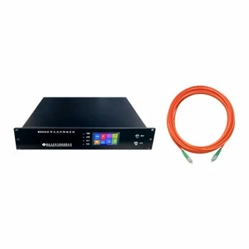

Products Description
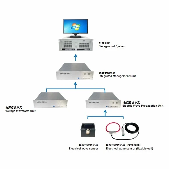
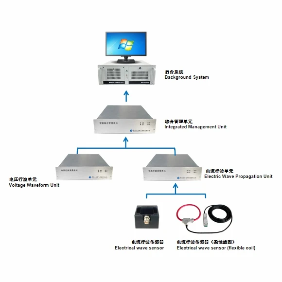
Our Cable fault location system captures transient current and voltage traveling waves at coordinated cable points. Time-difference analysis identifies the fault section, estimated position, and affected phase.
Technical Principle
Synchronized terminals detect the initial traveling wave generated by a cable fault. The master station compares wave-arrival times and known propagation velocity to calculate the fault distance, while waveform storage supports event verification and maintenance decisions.
Product Features
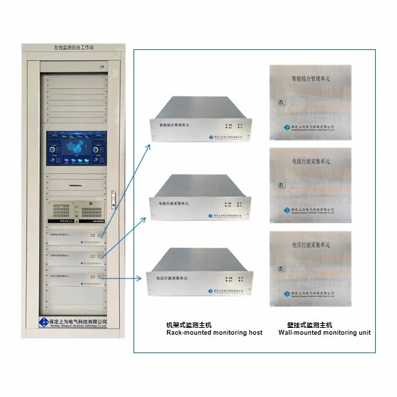
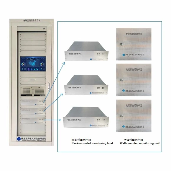
The Cable fault location system uses high-speed traveling-wave timing for precise cable fault positioning. Centralized and distributed formats fit dense substations and long field routes. Automatic recording preserves the current and voltage evidence around each event. Fault-section and phase indication can shorten field patrol and repair time.
Operating Conditions
Install the product in a clean, ventilated location without corrosive gas, conductive dust, water ingress, severe vibration, or strong impact. Provide reliable protective grounding, maintain the required electrical clearances, and use the rated auxiliary power supply. Confirm ambient temperature, humidity, altitude, enclosure protection, cable routing, and communication conditions before production and installation.
Product Parameters
|
Parameter |
Details |
|
Location error |
≤0.2%×L + 5 m, where L is the cable length between terminals |
|
Location accuracy |
≥99% |
|
Traveling-wave sensor band |
1 kHz-10 MHz |
|
Traveling-wave sampling |
≥100 MHz |
|
Traveling-wave current range |
0.1 A-100 kA |
|
Continuous record length |
≥1000 μs |
|
Waveform event time |
≤100 ns |
|
Fault-diagnosis success rate |
≥95% |
|
Main-station analysis time |
≤10 min |
|
Terminal protection |
IP68 |
Product Advantages
- The Cable fault location system uses high-speed traveling-wave timing for precise cable fault positioning.
- Centralized and distributed formats fit dense substations and long field routes.
- Automatic recording preserves the current and voltage evidence around each event.
- Fault-section and phase indication can shorten field patrol and repair time.
Main Applications
The Cable fault location system is used for high-voltage cable circuits, cable tunnels, cross-bonded routes, and T-connected networks.
It serves utility transmission cables, industrial cable systems, and urban underground networks.
Two end terminals cover up to 10 km in the stated configuration, with extra terminals for longer routes.
Components
|
Part |
Function |
|
Traveling-wave sensors |
Couple transient current or voltage signals from the cable circuit. |
|
High-speed acquisition units |
Digitize and time-stamp the transient waveforms. |
|
Management and timing unit |
Synchronizes terminals and calculates the fault position. |
|
Platform software |
Displays events, sections, waveforms, phases, and alarms. |
FAQ
Q: What information is needed for model selection?
A: Provide the route length, cable joints, bonding method, terminal locations, branches, and communication coverage.
Q: What should be checked before installation?
A: Install paired monitoring points with correct sensor direction, synchronized timing, grounding, and protected communication paths.
Q: How can the device or system be integrated?
A: The device supports 4G, APN private network, optical fiber, or carrier communication in the stated architecture.
Q: Which options should be confirmed before production?
A: Confirm centralized or distributed design, terminal quantity, power method, sensor interfaces, and platform connection.
Hot Tags: cable fault location system, China cable fault location system manufacturers, suppliers, factory, Cable Fault Location System, Cable Grounding Monitoring System, Fiber Optic Distributed Temperature Sensing System, integrated cable monitoring system, Overhead Line Fault Locator System, Smart Cable Grounding Box